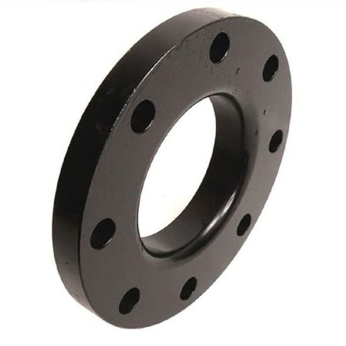
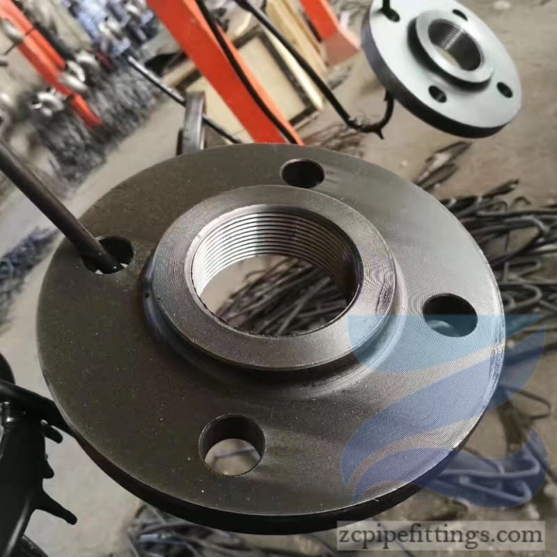
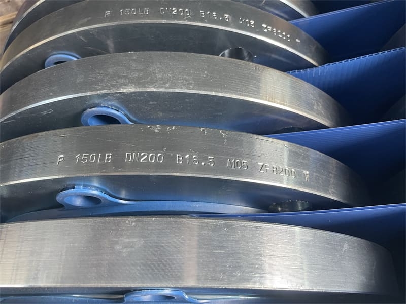
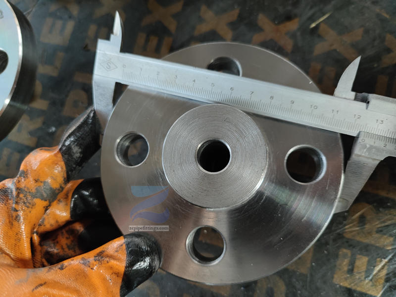
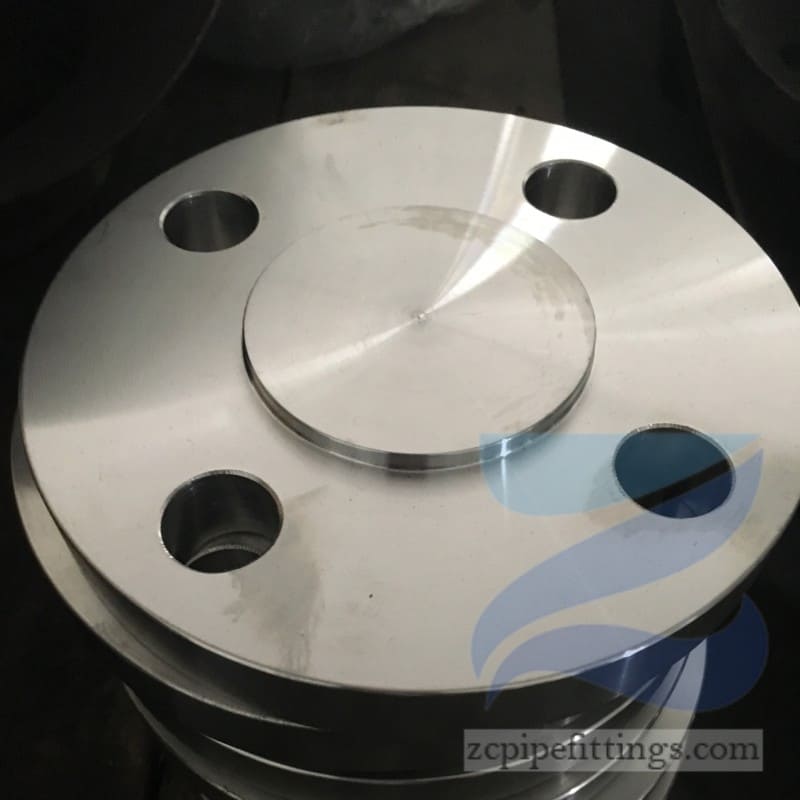
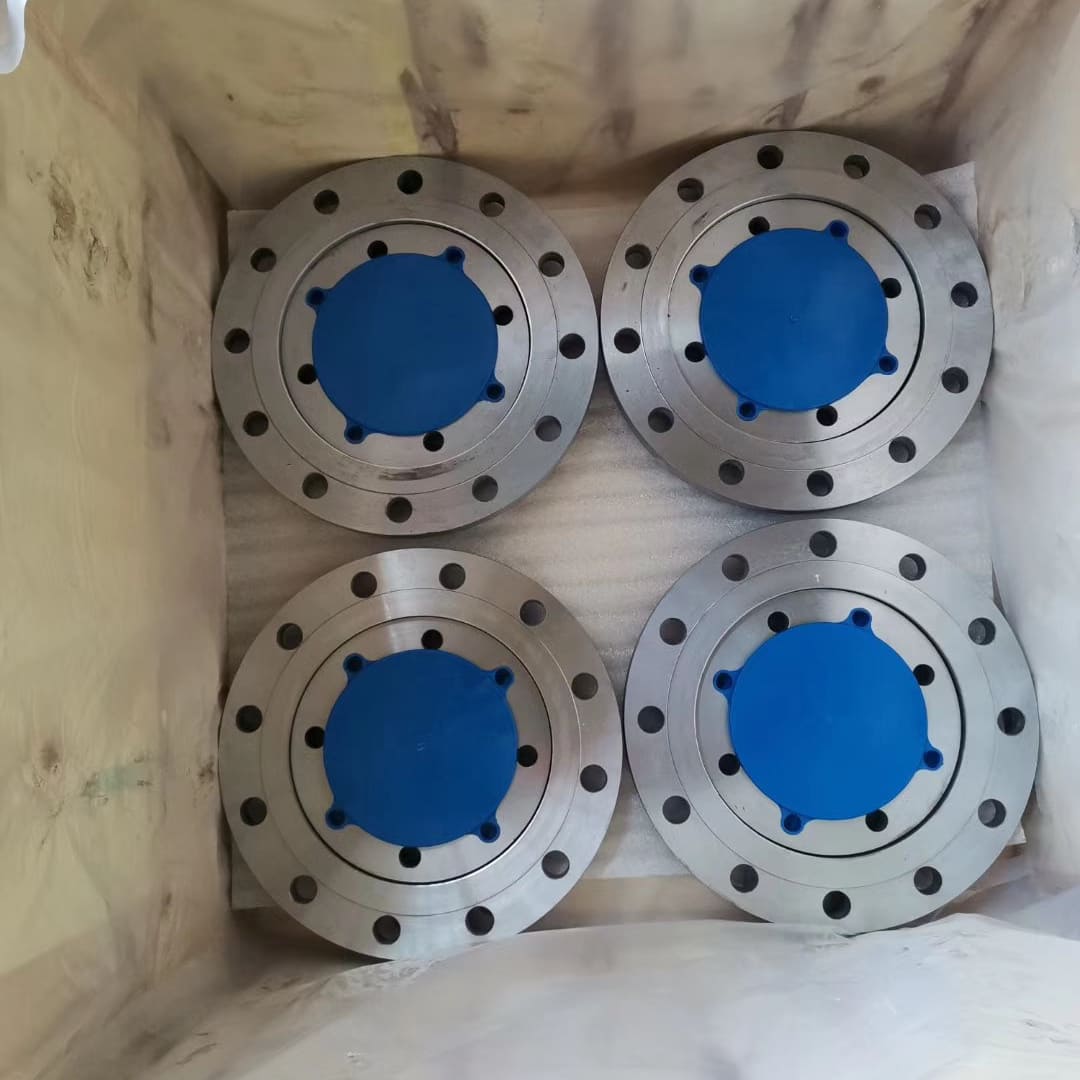
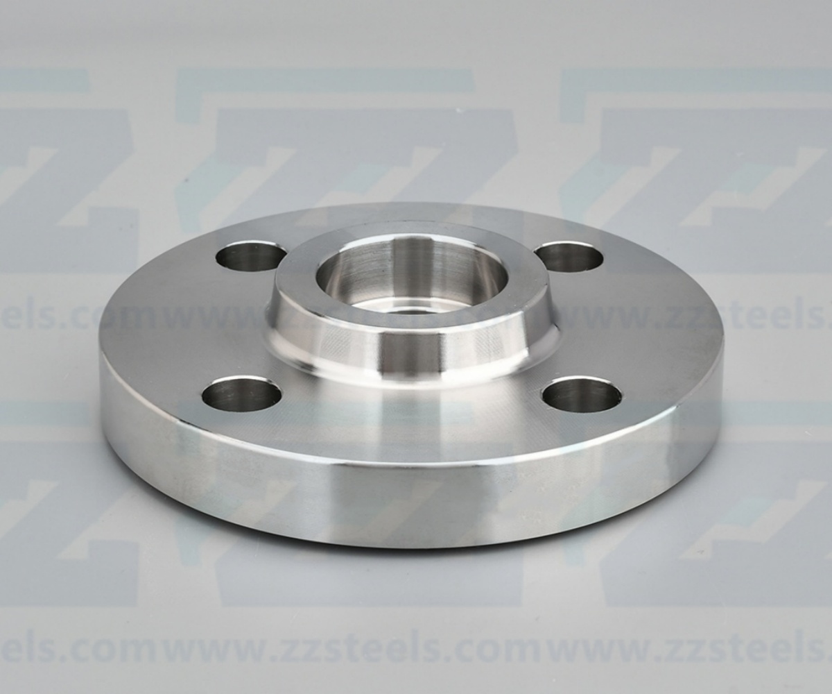
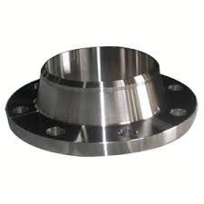
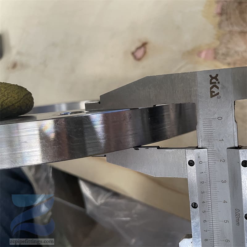
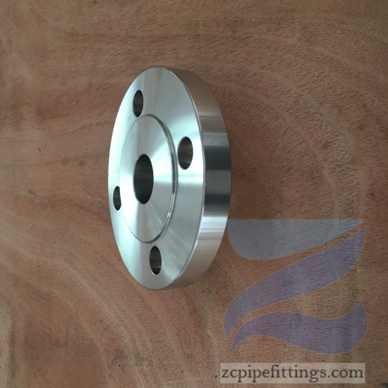
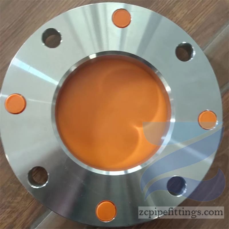
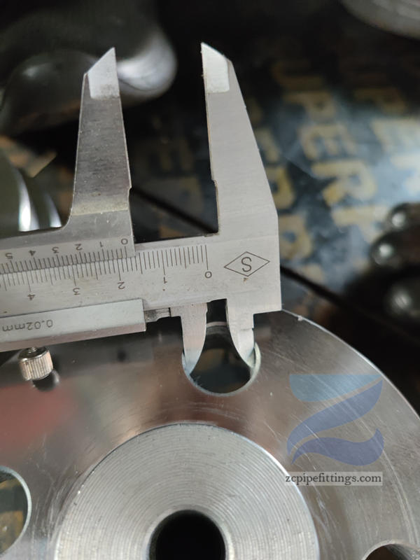
Carbon Steel Lap Joint Flange
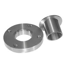
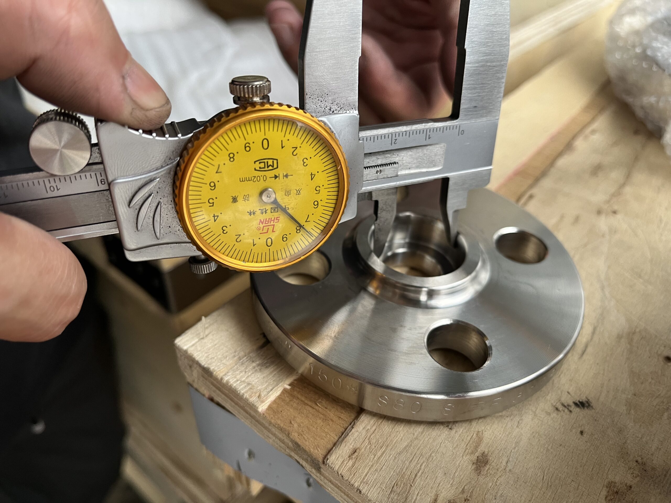
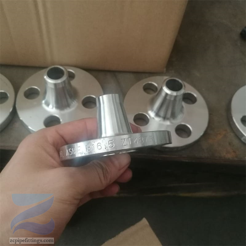
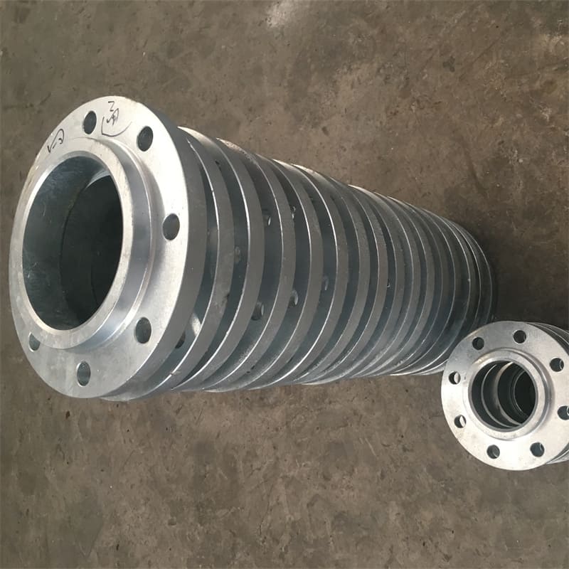
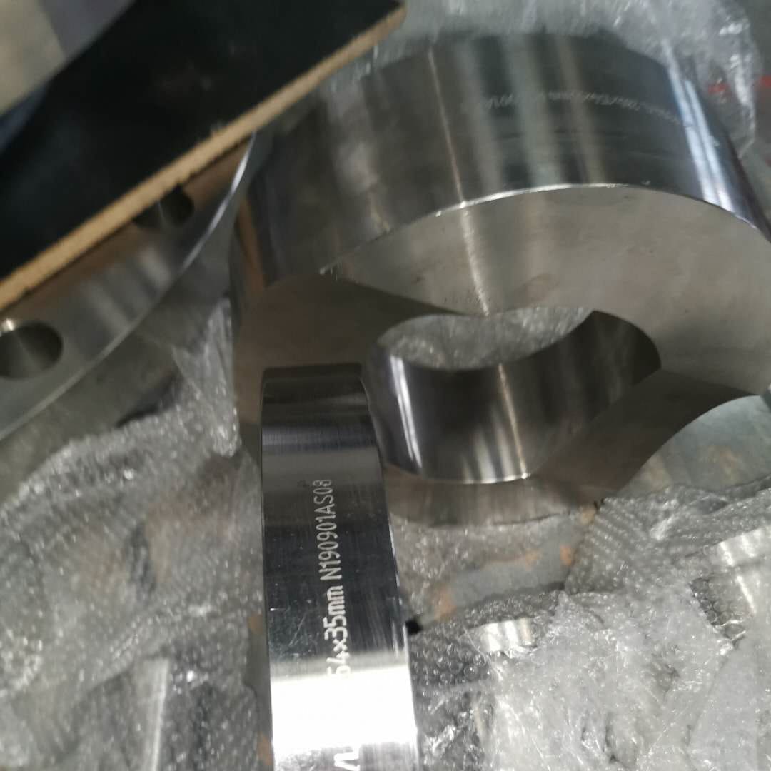
The lap joint flange is put on the pipe end by flanging, steel ring to put the flange on the pipe end. The flange can move on the pipe end. The function of the flange is to press them tightly. Since it is blocked by the flanging, the lap joint flange does not contact the medium.
The lap joint flange is put on the pipe end by flanging, steel ring to put the flange on the pipe end. The flange can move on the pipe end. The function of the flange is to press them tightly. Since it is blocked by the flanging, the lap joint flange does not contact the medium.
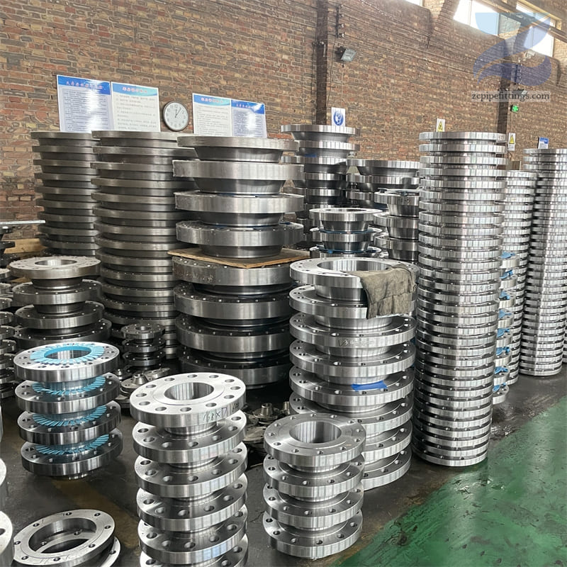
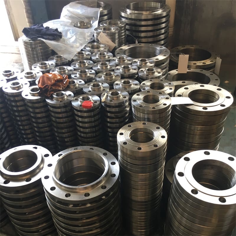
Carbon steel lap joint flanges are widely used in many fields, such as construction facilities, petrochemical industry, thermal power plants, pharmaceutical industry, and shipbuilding. Pipes and equipment in these fields often need to withstand different pressures, temperatures and media, and the diversity and adaptability of carbon steel lap joint flanges enable them to meet the connection requirements under these complex conditions.
Specification of Carbon steel Lap Joint Flange
| Size Range | 1/2″ – 24” / DN15 – DN600 |
| Pressure Rating | Class 150, 300, 600, 900, 1500, 2500lb |
| Standard | ASME B16.5, EN1092-1 |
| Carbon Steel | ASTM A105 / A105N |
Dimensions of Carbon Steel Lap Joint Flange
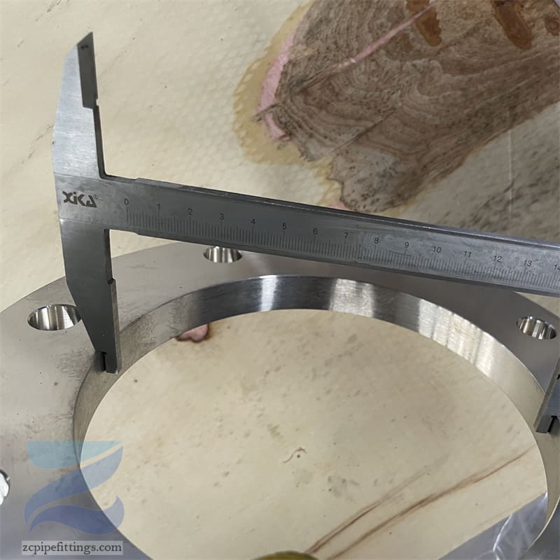
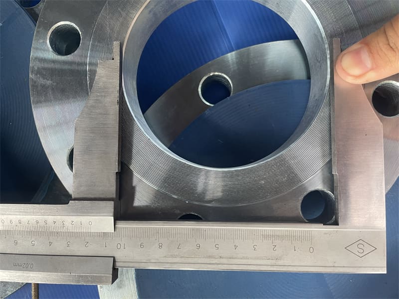
ASME B16.5 is the production standard for lap joint flanges. The standard has various dimensions, from 1/2″ to 24″, and the pressure levels are 150#, 300#, 600#, 900#, 1500#, 2500#.
Dimension of Class 900
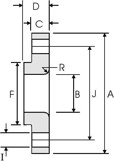
| Nominal Pipe Size | Outside | Overall | Inside | Flange | Overall | Lap | Hub | Number of | Bolt Hole | Diameter | kg/ |
| Diameter | Diameter | Diameter | Thickness | Length | Radius | Diameter | Holes | Diameter | of Circle | piece | |
| min | of Holes | ||||||||||
| in | in | in | in | in | in | in | in | in | |||
| mm | mm | mm | mm | mm | mm | mm | mm | mm | |||
| 1/2 | 0.84 | 4.75 | 0.9 | 0.88 | 1.25 | 0.12 | 1.5 | 4 | 0.88 | 3.25 | 1.71 |
| 21.3 | 120.6 | 22.9 | 22.3 | 31.7 | 3 | 38.1 | 22.3 | 82.5 | |||
| 3/4 | 1.05 | 5.12 | 1.11 | 1 | 1.38 | 0.12 | 1.75 | 4 | 0.88 | 3.5 | 2.3 |
| 26.7 | 130 | 28.2 | 25.4 | 35 | 3 | 44.4 | 22.3 | 88.9 | |||
| 1 | 1.32 | 5.88 | 1.38 | 1.12 | 1.62 | 0.12 | 2.06 | 4 | 1 | 4 | 3.4 |
| 33.4 | 149.3 | 35.1 | 28.4 | 41.1 | 3 | 52.3 | 25.4 | 101.6 | |||
| 1 1/4 | 1.66 | 6.25 | 1.72 | 1.12 | 1.62 | 0.19 | 2.5 | 4 | 1 | 4.38 | 3.85 |
| 42.2 | 158.7 | 43.7 | 28.4 | 41.1 | 4.8 | 63.5 | 25.4 | 111.2 | |||
| 1 1/2 | 1.9 | 7 | 1.97 | 1.25 | 1.75 | 0.25 | 2.75 | 4 | 1.12 | 4.88 | 5.28 |
| 48.3 | 177.8 | 50 | 31.7 | 44.4 | 6.4 | 69.85 | 28.4 | 123.9 | |||
| 2 | 2.38 | 8.5 | 2.46 | 1.5 | 2.25 | 0.31 | 4.12 | 8 | 1 | 6.5 | 9.78 |
| 60.3 | 215.9 | 62.5 | 38.1 | 57.15 | 7.9 | 104.6 | 25.4 | 165. 1 | |||
| 2 1/2 | 2.88 | 9.62 | 2.97 | 1.62 | 2.5 | 0.31 | 4.88 | 8 | 1.12 | 7.5 | 13.6 |
| 73 | 244.3 | 75.4 | 41.1 | 63.5 | 7.9 | 123.9 | 28.4 | 190.5 | |||
| 3 | 3.5 | 9.5 | 3.6 | 1.5 | 2. 120 | 0.38 | 5 | 8 | 1 | 7.5 | 11.3 |
| 88.9 | 241.3 | 91.4 | 38.1 | 53.8 | 9.7 | 127 | 25.4 | 190.5 | |||
| 4 | 4.5 | 11.5 | 4.6 | 1.75 | 2.75 | 0.44 | 6.25 | 8 | 1.25 | 9.25 | 19.2 |
| 114.3 | 292.1 | 116.8 | 44.4 | 69.85 | 11.2 | 158.7 | 31.7 | 234.9 | |||
| 5 | 5.56 | 13.75 | 5.69 | 2 | 3. 120 | 0.44 | 7.5 | 8 | 1.38 | 11 | 31.2 |
| 141.3 | 349.2 | 114.5 | 50.8 | 79.25 | 11.2 | 190.5 | 35 | 279.4 | |||
| 6 | 6.63 | 15 | 6.75 | 2.19 | 3.38 | 0.5 | 9.25 | 12 | 1.25 | 12.5 | 40.5 |
| 168.3 | 381 | 171.5 | 55.6 | 85.8 | 12.7 | 234.9 | 31.7 | 317.5 | |||
| 8 | 8.63 | 18.5 | 8.75 | 2.5 | 4.5 | 0.5 | 11.75 | 12 | 1.5 | 15.5 | 71.5 |
| 219.1 | 469.9 | 222.3 | 63.5 | 114.3 | 12.7 | 298.4 | 38.1 | 393.7 | |||
| 10 | 10.75 | 21.5 | 10.92 | 2.75 | 5 | 0.5 | 14.5 | 16 | 1.5 | 18.5 | 104 |
| 273 | 546.1 | 277.4 | 69.85 | 127 | 12.7 | 368.3 | 38.1 | 469.9 | |||
| 12 | 12.75 | 24 | 12.92 | 3.12 | 5.62 | 0.5 | 16.5 | 20 | 1.5 | 21 | 139 |
| 323.8 | 609.6 | 328.2 | 79.25 | 142.7 | 12.7 | 419.1 | 38.1 | 533.4 | |||
| 14 | 14 | 25.25 | 14.18 | 3.38 | 6. 120 | 0.5 | 17.75 | 20 | 1.62 | 22 | 161 |
| 355.6 | 641.3 | 360.2 | 85.8 | 155.4 | 12.7 | 450.8 | 41.1 | 558.8 | |||
| 16 | 16 | 27.75 | 16.19 | 3.5 | 6.5 | 0.5 | 20 | 20 | 1.75 | 24.25 | 194 |
| 406.4 | 704.8 | 411.2 | 88.9 | 165.1 | 12.7 | 508 | 44.4 | 615.9 | |||
| 18 | 18 | 31 | 18.2 | 4 | 7.5 | 0.5 | 22.25 | 20 | 2 | 27 | 267 |
| 457.2 | 787.4 | 462.3 | 101.6 | 190.5 | 12.7 | 565.1 | 50.8 | 685.8 | |||
| 20 | 20 | 33.75 | 20.25 | 4.25 | 8.25 | 0.5 | 24.5 | 20 | 2.12 | 29.5 | 334 |
| 508 | 857.2 | 514.4 | 107.9 | 209.5 | 12.7 | 622.3 | 53.8 | 749.3 | |||
| 24 | 24 | 41 | 24.25 | 50.5 | 10.5 | 0.5 | 29.5 | 20 | 2.62 | 35.5 | 618 |
| 609.6 | 1041.4 | 616 | 139.7 | 266.7 | 12.7 | 749.3 | 66.55 | 901.7 |
How to Install Carbon Steel Lap Joint Flange
First, align the carbon steel lap joint flange with the flange of the pipeline or other equipment, and ensure that the holes and bolt holes of the two flanges are aligned. Place a suitable gasket between the flanges. The material and thickness of the gasket should be selected according to the conditions such as the medium, temperature and pressure. The gasket should be placed on the sealing surface and ensure that it is flat and wrinkle-free. Finally, insert the bolts into the bolt holes of the flange one by one, paying attention to the direction and position of the bolts to ensure that the bolts can be tightened smoothly. Use tools such as wrenches to tighten the bolts initially, and be careful to apply force evenly to avoid partial over tightening or over-loosening. After confirming that the position is correct, use tools such as wrenches to tighten the bolts for the final time.

